40 Best Free Circuit Design Software For Windows
Here is a List Of Best Free Circuit Design Software for Windows. These freeware let you design digital circuits with a vast array of inbuilt components. Some of these circuit design software let you create schematic design, while some let you design PCB. Some of the PCB design software also let you make schematic design in a single package. Use these software to design circuits professionally, or for educational purposes.
The components available for you to design circuits include: Microchips, ICs, Logic Gates, Diodes, Transiters, Capacitors, Comparator, Pulse Generators, IGBT, Relays, TRIAC, LEDs, Amplifiers, Switch, Transformers, Relays, Circuit Breakers, Flip Flops, and many more.
The list also includes Circuit Simulation Software which after designing a circuit, simulates it to display numerical or graphical output.
You can also order online for the designed circuit through some of these PCB design software.
My Favorite Circuit Design Software:
Digital Logic Design and idealCircuit are two of the best circuit design software that I like. These two have extensive component libraries to let you design circuits easily. These two are also excellent circuit simulation software.
You can also checkout the list of best free CAD Software, Flowchart Software, and Markdown Editor.
idealCircuit
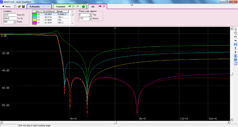
idealCircuit is one of the best free circuit design freeware. The interface lets you design analog circuits pretty easily. Apart from designing, you can also simulate a circuit to view its output. The UI has 3 different tabs: Schematic, Transient, and AC. Design circuit in the schematic tab, view the transient output in the Transient tab, and view AC parameters in the AC tab. The components to design circuit are available in different tabs where you can choose from a list of: Voltmeter, Ammeter, AC source, Resistor, Capacitor, Diode, Transistor,
Amplifier, Switch , Transformer , and Logic Gates.
After circuit design is complete, you can save your design in .ic format. There are various pre designed circuits available as well which you can open and run to view the output.
Digital Logic Design
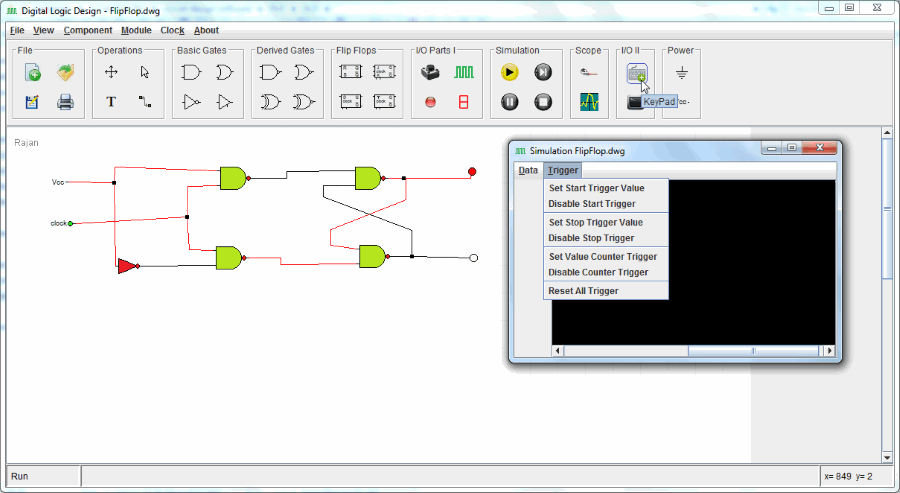
Digital Logic Design is a free standalone software to design digital circuits. It is a Java based program, and requires Java to be installed on your PC. You can add the following components to your design to form a digital circuit: Logic Gates, Derived gates, Flip Flops, input/Output parts, Simulation, Source, Ground, etc. Save your design as .dwg file.
After your design is complete, you can simulate the circuit, and view its graphical output with the help of Scope tool.
This circuit design software can be used for professional, as well as educational purposes to design Digital Logic, Computer Architecture, Embedded Circuits, etc.
PCBWeb
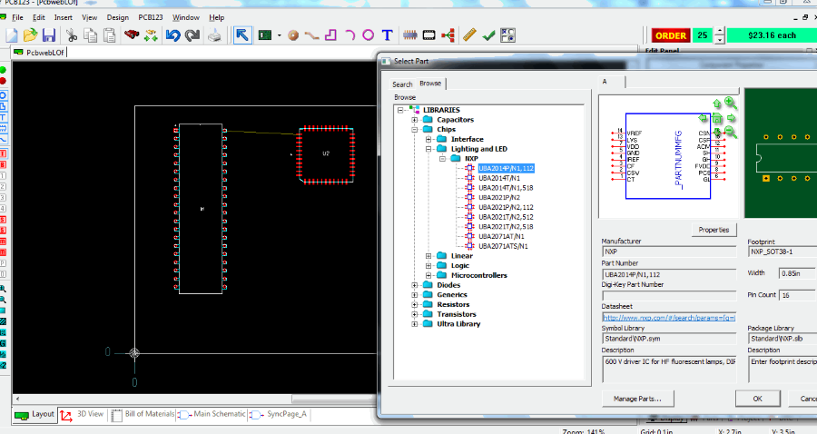
PCBWeb is a free PCB design software for Windows. It lets you design PCB on your computer and order it online to the manufacturer. Design your circuit with various components, like: Chips, Diodes, Resistors, Transistors, etc. When you create a new file for PCB design, you are asked for Board Name, Board Size, Layers Required, Silk Screen, Material Thickness, etc. A new tab appears on the UI with a blank sheet to design your circuit. Begin adding components from the toolbar (Ctrl+K). A new window opens where you can search or browse for a part to add in the circuit. When you select a component, the window displays the details of that part, like: Manufacturer, Part number, Footprint, Size, Pin count, etc.
You may also add footprint of different parts to the PCB, add connections, Shapes, Free style routing, Pin, Cut-outs, and much more. Add text to label parts, pins, connections, etc.
The Edit Panel is available on the right side of the UI. At the bottom of the workspace you will find toggle option between Layout, 3D View, main Schematic, etc. View the price of the designed circuit on the top right part of the UI. This circuit design software lets you Save the circuit on your device in .123 format. Print the PCB design if you want. Go to the Help tool for User Guide and Reference Manual.
ZenitPCB
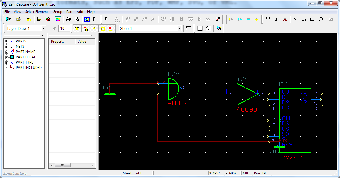
ZenitPCB is a free to use circuit design software. Use this freeware to design electronic circuits with various circuit components. Create a new design sheet to begin designing a circuit. A black colored board with grid appears where you can place your components. Right click on the board to add Parts, Wire, Signal Ref, Global Net, and Text. Click on the Parts option to open a library of parts. Here you will find different Diodes and ICs; select a part and click on the place to apply it on the board. Click on a placed component to view its properties in the panel available on the left side of the screen. Once you have designed your circuit, go to View>ERC (Electrical Rule Check) to check if there’s no error in the circuit design.
You can save your project in . ZSC format. A printout of the circuit can be taken if you want. A report of the project can also be exported in TXT format. This report includes Project name, Author, Number of Parts, Pin count, etc. A User’s guide is available in PDF format in the Help menu.
BSch3V
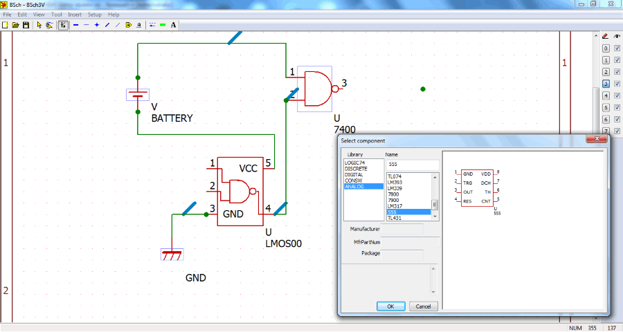
BSch3V is an open source circuit design software for Windows. It is a simple freeware with easy to use UI. Open a new document to build a circuit. Click on the Component icon to access the list of components. The library lets you choose from Logic, Discrete, Digital, Consw, and Analog components. Select a component, and click on OK to place it on the circuit board. Add Bus, Wire, Junction, Entry Bus, etc. to connect the components. This PCB design software lets you work on a 7 layered sheet. You can insert any image on the circuit if you want to.
There is an option to change the sheet size as well. Go to Setup> Sheet size to choose from a sheet size of 640×400 to 3250×2250. Save your document as .CE3 format. You can even export the circuit as image in .BMP and .PNG formats.
KiCad EDA
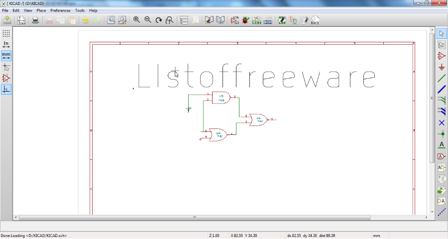
KiCad EDA is a cross platform circuit design software for Windows, MAC OS X, and Linux. To design a circuit you will have to create a new project and open the Schematic Editor. Opening a new project creates a new directory. Go to the Schematic Editor tab and begin designing. Click on the Place Component option to select a part and place it on the designing area. These components include: Microchip, Memory, Display, Audio device, Xilink, Power, Transistors, DSP, and many more. Add more components like: Ground, Wire, Bus, Junction, etc. to connect the main components.
Save the designed sheet, which you can find in the directory you created. Render grids on the sheet, and change cursor pointer to help you design circuit easily. Print option lets you Preview and Print the designed sheet directly from this circuit design freeware.
The Schematic Library Editor lets you edit and change the properties of various components. Click on PCB Editor tab to design printed circuit board. With the help of PCB Footprint Editor, you can add footprint to PCB according to various components. A Bitmap2Component converter, and a PCB Calculator are also available in this software.
CircuitMaker
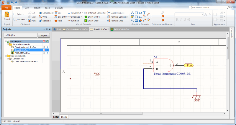
Circuitmaker is another free software to design PCB circuits on Windows. To be able to use this fantastic circuit design software, you will have to sign up on its website first. Launch the application and sign in with the ID. It is a desktop based online software which needs internet to work. Create a new project to start circuit design on this EDA software.
It has a very interesting feature of collaboration, where you can work on project as team. Add team members to your project, and all members can collaborate to work together on an electrical design project. To create a Team project, select the Team option while creating project, assign its attributes, and then add members.
The design is only saved online, and not on your device. When your project is complete on this circuit design software for Windows, you can release it to be viewed by anyone, or submit to collaborate with selected members.
Fritzing

Fritzing is an open source circuit deign software for Windows. This is a free software which needs no installation. When you open this freeware, you land on a welcome page. The welcome page asks if you want to create a design, or open example. On the right side of the UI, you can see the Tools menu. The list of components include: ICs, Resistors, Diodes, Gates, Switches, Wire, Junctions, etc. Click on a component to view its description at the bottom. You can even add a Note, or rotate the PCB board.
When the PCB design is complete, save the file as .FZZ format. You also have the option to export circuit design as PDF or Image. You can view your design is various modes: Breadboard, Schematic, PCB, and Code. The Code mode lets you write your own code, and feed it to the ICs such as Micro Controllers or Micro Processors. An online Help page is available in case you are having any kind of trouble with this free circuit design software.
DesignSpark PCB
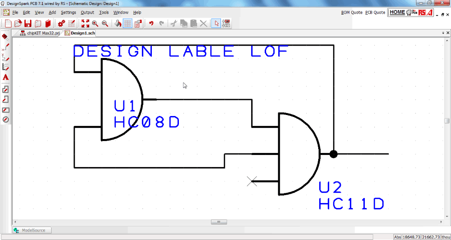
DesignSpark PCB is another free circuit design software for Windows. To be able to use this PCB design software, you need to be connected to the internet. When you create a new circuit design, you will be asked to choose if you want to create a Schematic Design or PCB design. You can also create a project if you want to design various circuits under one project.
You can open and edit files in different tabs. Press F3 or click on the Components icon to open the list of components from Library. There is a huge list of components, which include: AC Source, Logic Gates, Capacitors, Comparator, Pulse Generator, Diodes, Inductors, Opamps, Sine Generator, Zener Diode, and many more. You can also add Shapes, Connections, Text, etc. Schematic diagrams are saved as .sch while PCB designs are saved as .pcb.
This circuit design software can also generate a report of items used in the designing of circuit, and export it in .rtf format. One of the awesome features of this freeware lets you convert a schematic design to PCB design.
PCBArtist
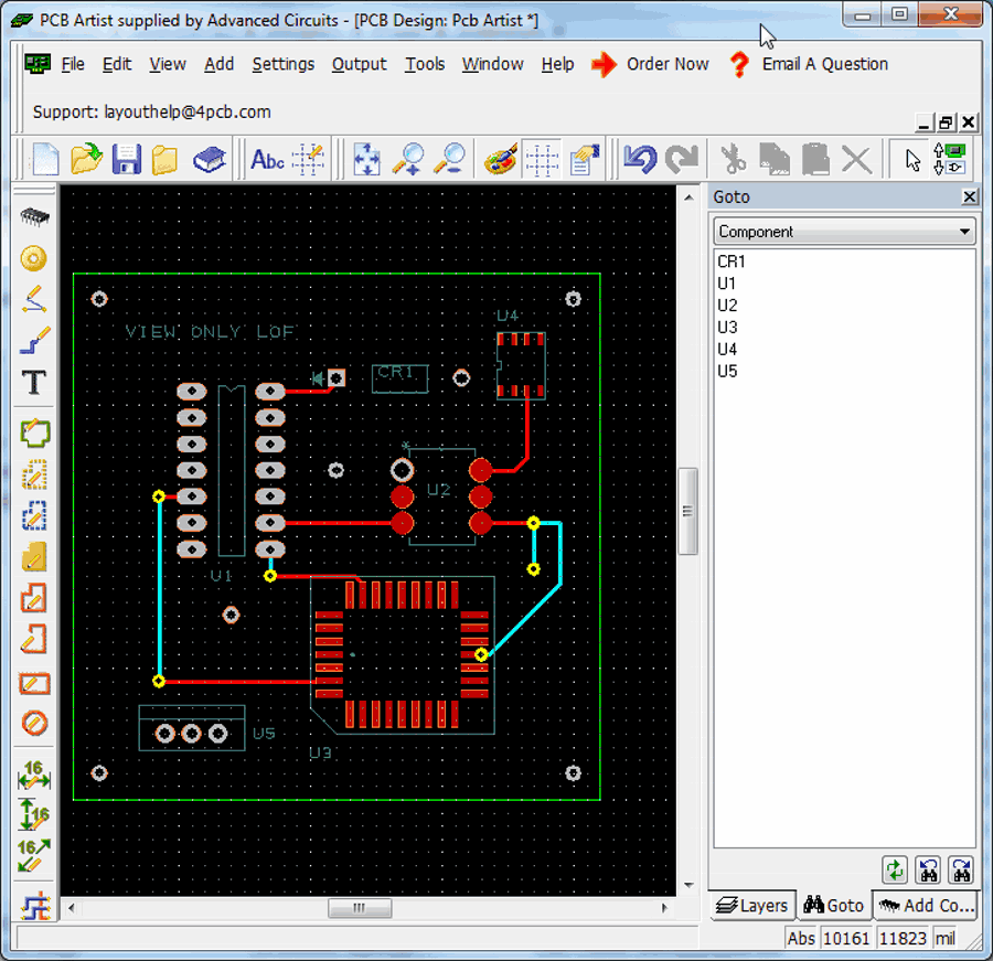
PCBArtist is one of the best PCB design software available for free. This PCB design freeware gives you option to add various components and connect them to form a circuit design. Click F8 to access component library. These components include: EEPROM, IGBT, Relays, TRIAC, LEDs, Switches, Diodes, Capacitors, and various other ICs. While selecting a component, click on it to view its design and pin configuration. Board dimensions can be set as well. The right panel of the UI displays layer options and list of components. After designing is complete, save your design in .pcb format.
There is an option to order the designed PCB circuit. Click on Order Now option to view the options to complete the order.
ProfiCAD
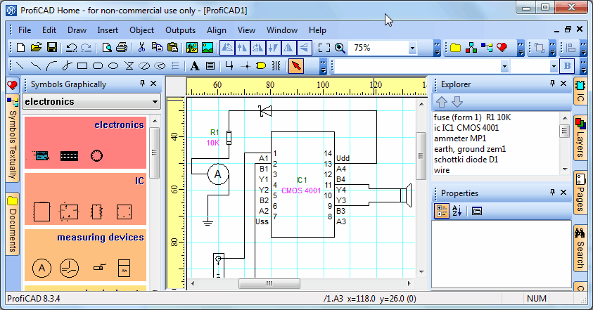
ProfiCAD can be used to design circuits on Windows. It can be used for designing electrical, electronic, and house circuits. Find components on the left side of the UI. These components include: Ampliers, LCD, Measurement Devices, Resistors, Indictors, Rheostats, Transistors, Diodes, Circuit breakers, Switches, Transformers, and other electrical installation, house electrical devices, distribution devices. When you select a device and add it to your design, you can click on it to view its properties on the left panel of the UI.
Grids are available on the workspace to let you create clean circuit diagrams. Save your circuit design in .sxe format. Preview and print your design directly from this circuit design software.
It is not available for commercial use free of cost; you can only use it for non commercial purposes. Visit the website to know more.
Logisim
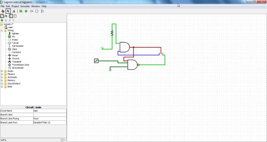
Logisim is an open source circuit design software for Windows. To design a circuit, you need to create a new file and add components on the work field. The components panel is available on the left side of the UI. These components include: Logic Gates, Arithmetic Circuit, Memory, Multiplexer, Demultiplexer, Input/Output Circuits, Splitter, Pin Probe, Clock, Power, Ground, etc. Save your design as .circ file. This software to design circuit also lets you simulate a circuit after you have designed it.
Go to the help menu to access the complete help documentation.
TinyCAD
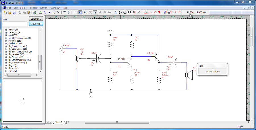
TinyCAD is another open source free software to design electrical circuits. Use any of the following components to design circuit: Logic Gates, Capacitor, Diodes, Power sources, Micro controllers, Relays, Switches, and other important components. All these components are available on the UI’s left panel. Use the wires, symbols, text, and shapes to connect and finalize the circuit. This circuit designer software also lets you change color of wires, junctions, text, pins, etc. After completion of your design, save your file in .dsn format.
Go to the Special menu to access features like creating a list of components used in the circuit design. The list is saved in .net format.
FidoCadj
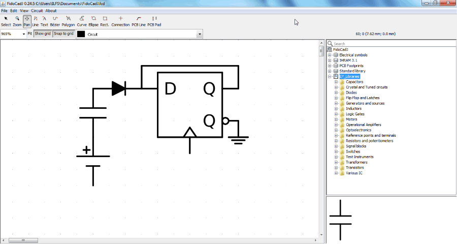
FidoCadj is cross platform open source circuit design software available for Windows, MAC, and Linux. This Java based circuit design software is absolutely free to use.
The components available in this software to design circuits are divided into four categories: Electrical Symbols, IHRAM, Standard Library, and EY_Library. You will find the following components available in the library: Actuators, Circuit Breakers, Conductors, Analog ICs, Basic Symbols, Civil Electrical Wiring, Digital ICs, Diodes, Transistors, etc. The library is located on the left side of the interface where you can look for a component by browsing or through the search box. Click on a component to set parameters, values, name, etc.
Save the circuit design in .fcd format after designing is complete. An option to export the schematic diagram in .png format is also available.
CEDAR Logic Simulator
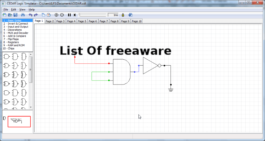
CEDAR Logic Simulator lets you design basic as well as high end logic circuits with the help of logic gates. This open source circuit design software is free to use, and also lets you simulate designed circuit. Add components like: Basic Gates, Invertors, Connectors, Input/Output, Mux, Decoder, Flip Flops, RAM, ROM, Chipset, etc. You can even set simulation time to test your circuit design. Save file in .cdl format, or export the design as bitmap image.
Logic Gate Simulator

Logic Gate Simulator is another good open source circuit design software. As the name suggests, this is primarily a software to design circuits with logic gates. The available components are: AND, OR, NOT, Buffer, NAND, NOR, XOR, XNOR, I/O Gates, User Input, User Output, Numeric Input, Numeric Output, etc. Simulate your design once designing is complete; use custom simulation speed. View the output of the simulated circuit in the Oscilloscope available.
Save your circuit design as .gcg file, or save it as image in .png format.
DipTrace
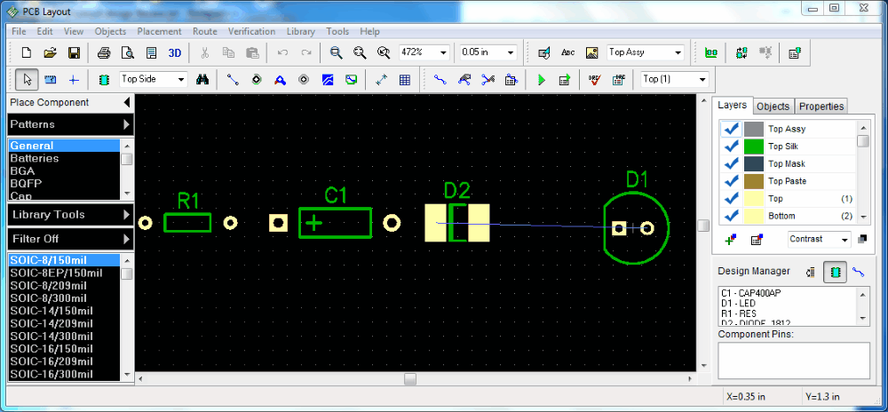
DipTrace is a free PCB design software for Windows. There are 4 different tabs available on the UI of this circuit design freeware: Schematic Capture, PCB Layout, Component Editor, and Pattern Editor. Create schematic circuit design in the Schematic Capture tab, and view the designed circuit in PCB form in the PCB Layout tab. The Component Editor and Pattern Editor let you change the pins and edit the components in schematic and PCB layout respectively.
Now, there is a vast set of components which you can use to design your circuit, like: Discrete SMD, Symbols, Net Ports, Batteries, Buzzers, Con USB, Diodes, Bridges, LCD Display, Microphones, Logic Gates, ICs, and many more. Save schematic design as .dch file, and PCB as .dip file.
After designing the circuit, click on the Verification option in the menu bar to check electrical rules.
You can use this software for free for non-commercial purposes, but you will have to pay for the pro version if you want to use it commercially.
Electric

Electric is a simple circuit design software which runs on Java. It requires Java 7 or higher to be installed on your computer to operate. To create a new design on this freeware, you need to open a new Library, create a new Cell, and select Schematic option. Go to the components tab to select from list of tabs: Logic Gates, Transistors, Diodes, Power Sources, Ground, Wires, etc. You can even copy a design from one sheet to another.
There is an explorer tab which displays all the design sheets available in the Libraries. The libraries are saved in .jelib format.
Deeds

Deeds, also known as Digital Electronics Education and Design Suite is a freeware to design electronic circuits on you computer. Use components such as: Buses, Wire, Input/Output Components, Logic Gates, Arithmetic Circuits, Filp Flops, Micro Computers, etc. to design circuits. Simulate your design by pressing F9 button, press F8 to show timing diagram simulation.
An option to check electric rule is also available on this freeware. Export your design as .vdhl and .fpga formats. Go to the learning demo section to know more about this free circuit designer software.
Download LTspice IV
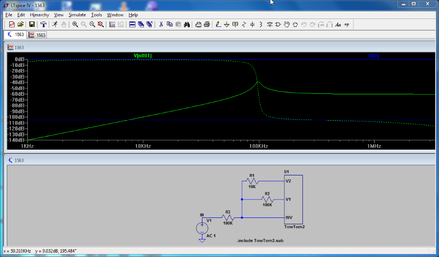
Download LTspice IV is a cross platform free schematic design software for Windows and MAC. You can use the components available in the library to design circuit, edit them, or even create a new symbol to use in your circuit diagram. Find the following components available here: Diodes, Capacitor, Ground, Wires, Text, Inductor, Resistors, etc. Connect the components and click on the Run icon to simulate the circuit. You can even view the output waveform though this awesome circuit design software.
Hades
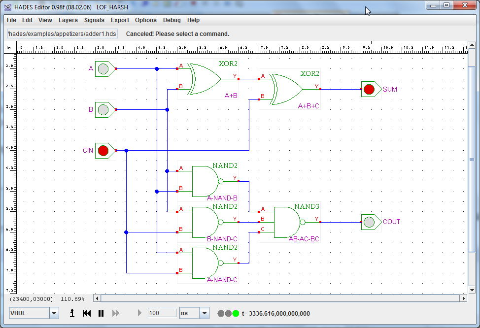
Hades is a circuit design and simulation software for Windows. This open source software has a bunch of simple as well as complex components. Use these parts to design and simulate a digital circuit. The components available are: Logic Gates, ICs, Vcc, Ground, Hexa Switch, Clock Generator, Flip Flops, RTL, etc.
Connect the components to form a design, and save them in .hds format. Run simulation to view output. Go to the Help menu where you will find various circuit examples.
EAGLE
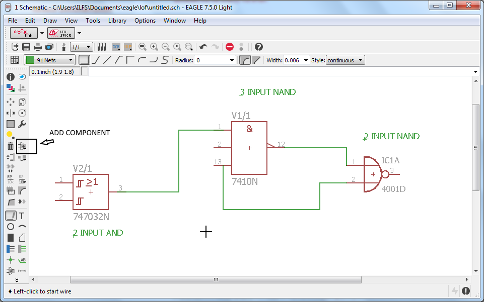
EAGLE offers free version for non commercial use to learn circuit design. To create a new schematic diagram you will have to create a new project, and then open a new schematic file under it. Find a huge list of components to build circuit: Diode, Supply, Symbols, Opams, Optos, Filters, Comparators, etc. You can click on each component to view its attributes, like: property, name, symbol, etc. You can also rotate, copy, or delete a device by right clicking on it.
Visit the tool menu for Electrical Rule Check, Errors, Statistics, etc. Import an Eagle circuit drawing and bitmap files, and Export Net-list, Part-List, and Pin-List.
Simulide
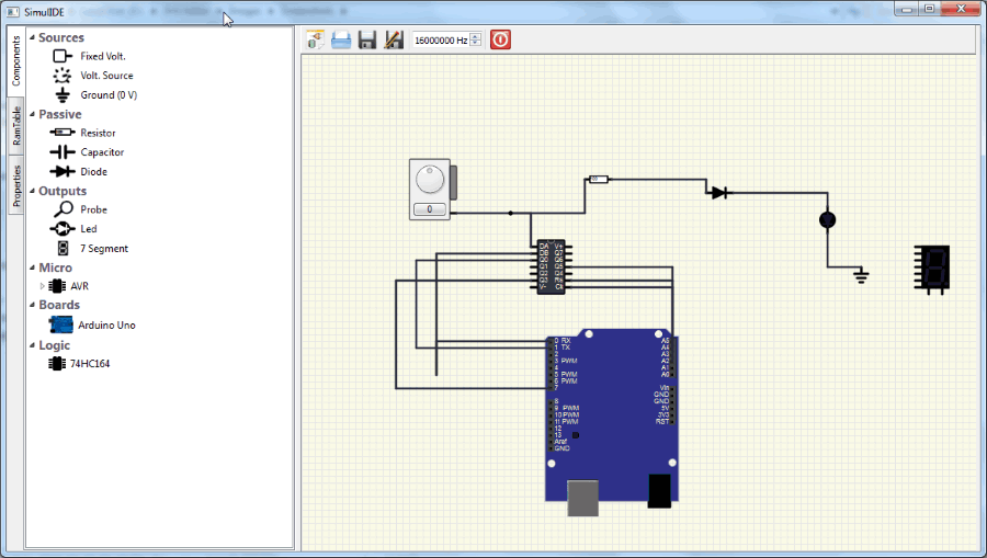
Simulide is a simple and basic circuit design software. It has basic electronic components to build circuits, and test them by simulation. Make circuit with the help of components such as: Resisters, Capacitors, Diodes, Voltage Sources, Ground, Probe, LED, etc.
Circuits are saved in .simu format. This is a basic software which can be used for educational purposes.
FreePCB
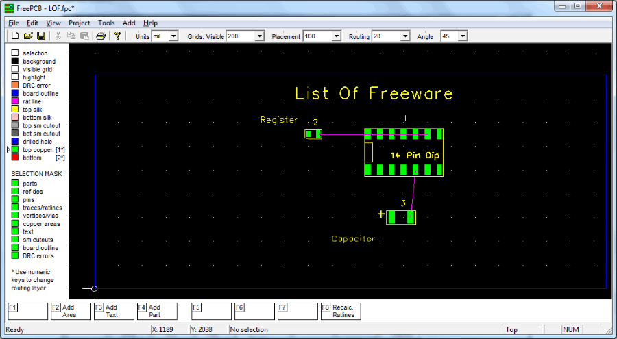
FreePCB is an open source PCB design software. It lets you design circuits in different layers, making circuit design an easy job to accomplish. Begin designing a circuit with these components: Resistors, Capacitors, Inductors, LEDs, Connections, Transistors, ICs, Connectors, etc. Activate the Auto Save function under the Project menu. Go to the Parts option under project menu to view all the parts with info, click on Nets option to view all the connections.
Add up to 16 copper layers, set board size up to 60×60 inches, apply footprints, and make use of Design Rule Checker.
ADS
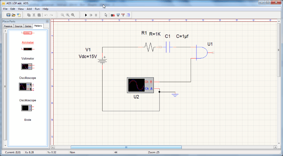
ADS is an open source circuit design and circuit simulator software. You will get a long list of components here: Resisters, Capacitors, Inductors, Voltage sources, Battery, Voltage AC, Logic Gates, Tristate Buffer, Ammeters, Voltmeters, Oscilloscopes, Bodes, and many more. Simulate the circuit after you have designed a circuit by pressing F9 or by clicking on Simulate icon. This software has easy to understand UI, and is simple to use.
You might face problem while installing this freeware, try to install it in a drive other than the default one.
QSapecNG

QSapecNG is a QT Framework based, open source software to design analog circuits. Design and run your circuit with this freeware. Components to design circuits available: Resisters, Capacitors, Inductors, Voltage source, Current source, CCVS, VCCS, CCCS, Operational Amplifiers, Ideal Transformers, Mutual inductors, etc. While you simulate your circuit, this software displays circuit activity on the right panel of the User Interface. View the components, and their properties on the left panel. Look for measurement tools like Voltmeter and Ammeter in the Tool menu.
SmartSim
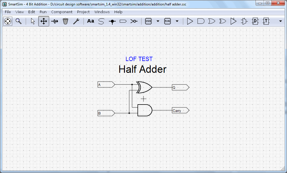
SmartSim is an open source multi platform digital circuit design software for Windows and Linux OS. Available components to design circuits: Logic Gates, D/F/T Flip Flops, Clock, Memory, LEDs, Multiplexers, Wires, Connectors, etc. The edit option lets you delete component, invert component, add text, drag component, and change orientation. Check circuit validity after designing is complete, and simulate it through the Run option in Toolbar. Export your design as .png, .svg, or .pdf.
CircuitMod
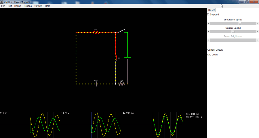
CircuitMod lets you create simple as well as complex digital circuits for free. This open source freeware is written in Java. Add components, build circuit, simulate, and view output with waveforms. You can Right Click on the workspace to access the component menu. The components available are: Resisters, Capacitors, Inductors, Passive Components, Active components, Input/Output Devices, Logic Gates, ICs, Display Devices, and many more.
After simulation, you can view the output at any point on the circuit by right clicking the component>view in scope. Click on Stack All option in the scope window to view the waveform of all components together. Click Unstack All to view individual waveforms. You can also vary the simulation speed of the circuit.
Go to the Circuits menu to view sample digital circuits.
Solve Elec
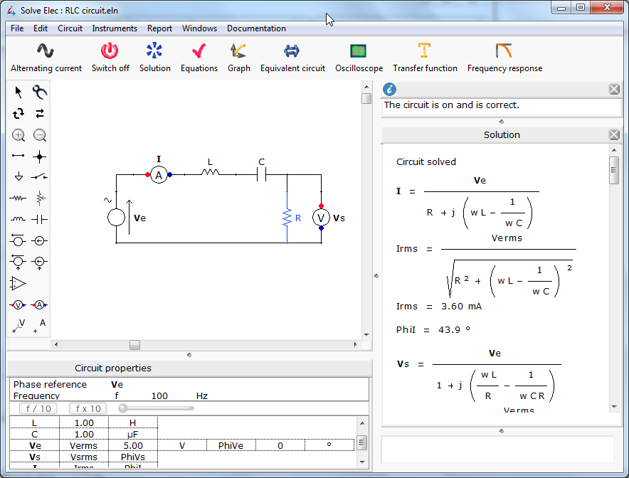
Solve Elec is a unique circuit design software which can be used to solve electrical circuits. Create simple designs with the available components, add values to them, and find the correct value for the device with unknown value. The components are available on the left panel, like: Resisters, Capacitors, Inductors, Diodes, LEDs, Ammeters, Voltmeters, Amplifiers, Transisters, Current source, Voltage source, etc.
After designing a circuit, click on Switch On button to check if its correct. Click on Solution to show the solution of circuit after solving it. Click the Equation button to view all the equations applied in the circuit. All of these parameters are displayed on the right side of the UI.
Other major options available here are: Graph, Equivalent Circuit, Oscilloscope, Transfer function, Frequency response, etc.; access them in the Toolbar.
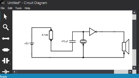
Dia Diagram Editor

Dia Diagram Editor is a versatile diagram maker and editor. It lets you design a huge variety of diagrams which includes electrical/electronic circuits and diagrams. Go to the Tools menu to access the components to design digital circuit. You will find components to design digital circuits under various categories, like: Electrical, Electronic, Logic Components, etc.
It has layers option which lets you create diagrams pretty easily; you can also move the layers up/down. Save your diagram in .dia format.
AACircuit
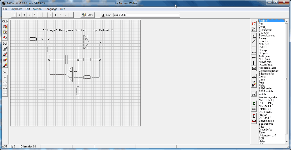
AACircuit is released under Beerware license. It uses ASCII symbols to create circuit designing components. The component library is available on the right side of the interface. Find components like: Logic Gates, Buffers, Battery, Transformers, Amplifiers, Transisters, Lamps, Fuse, LED, Crystal, Bridge Amplifier, JK/D Flip Flops, Triacs, Vcc, Gnd, SCR, etc. Complete the circuit and save it in .txt file format. It is one of a kind circuit design software for Windows.
Digital Works

Digital Works is a standalone circuit design freeware. It provides a simple interface to design digital circuits. Use the following components to develop a circuit: And, Or, Not, Xor, Buffer, Battery, Vcc, Gnd, RS/JK Flip Flop, Memory, Sequence generator, Clock, Switch, Wire, etc.
Save your circuit as .dwm file. You can even simulate the designed circuit. Use these shortcuts to simulate: Run: F9, Stop: F10, Pause: F11. Options to set Clock Speed is also available.
MultiMedia Logic
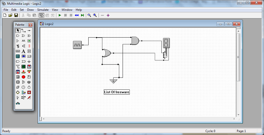
MultiMedia Logic is another easy to use circuit design software. Design your circuit, save it, and run simulation to test it. Use these components to design digital circuits: Gnd, Oscillator, Inverter, Flip Flop, Signal Receiver, Bus, 7 Segment Display, MUX, ALU, Memory, etc. You can set simulation speed if you want to.
Use desired background color. Save your design in .lgi format or directly print it from the software.
PECS
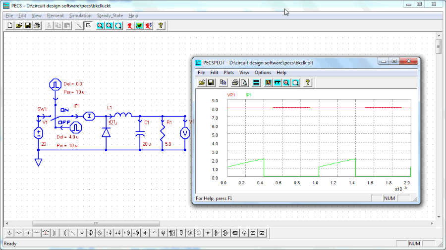
Design digital circuits and simulate them with PECS. It is a free software with an intuitive interface. These circuit design components will help you to design digital circuits: And, Or, Not, Gnd, Switch, Wire, Resisters, Capacitors, Inductors, Diodes, LEDs, Transisors, Clocks, Limiters, Labels, Oscillators, CCCS, VCCS, etc.
The simulator option is available in the Simulation menubar. Click on a component to set its value. Save the circuit as .ckt file.
GeckoCIRCUITS
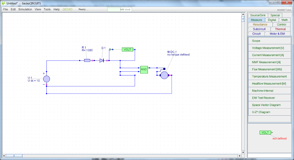
GeckoCIRCUITS is available for free to design digital circuits. This is a portable software and needs no installation.
The components panel is present on the right side of the UI, and are categorized as:
- Circuit: AND, OR, NOT, Gnd, Switch, Wire, Resister, Capacitor, Inductor, Diode, Transistor, MOSFET, etc.
- Motor: CD Machine, PMSM, Induction Machine, etc.
- Reluctance: NonLinear Reluctance , Inductor Reluctance.
- Mesurement: Scope, Voltage, Current, Temperature, EMI TEST, etc.
- MATH: Addition, Subtraction, Multiplication, Division, etc.
- Shink: Signal Source, Constant Source, Gate Control, Dtc, etc.
Double click on any component to view its properties. Save a designed circuit as .ipec file.
This circuit design software is written in Java, and requires Java version-8 to function.
CircuitMaker (Student Edition)
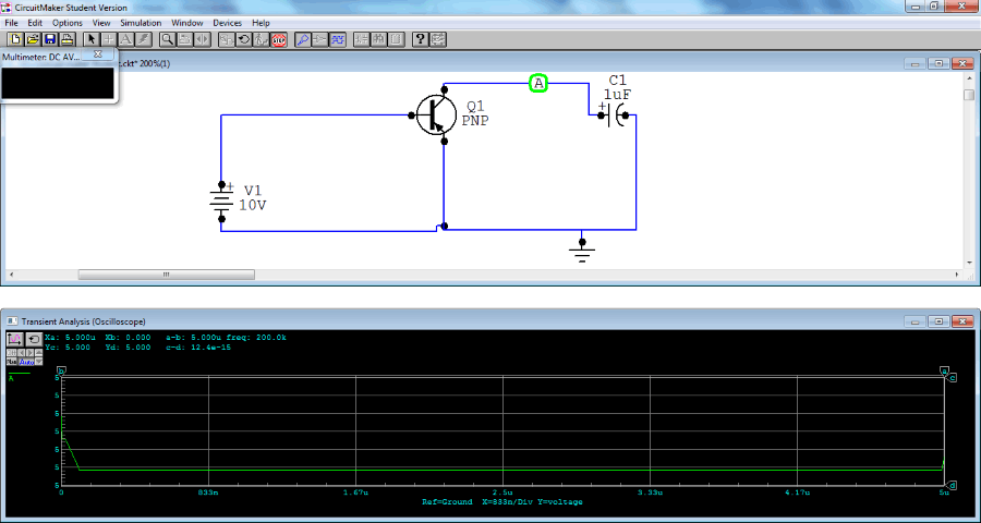
CircuitMaker (Student Edition) is a lite version of the circuit design software CircuitMaker. It is free to use, and has been developed to learn circuit design. Use the following circuit components to design circuit: Active component, Passive component, Regulator, Relay, Amplifier, Buffer, Analog, Capacitor, Comparator, Diode, Inductor, Fuse, Math function, Modulator, MOSFET, Motors, etc. Simulation of circuit can be carried out after the design is complete. You can also view the output waveform.
Circuit Diagrams
Circuit Diagrams is an open source circuit designer for Windows. To create a circuit diagram with this software, use various circuit design components available here. The list of components includes: Resisters, Variable Resisters, Potentiometers, Thermistors, LDR, Capacitors, Variable, Timer, Logic Gates, Diodes, Zener Diode, LEDs, Transistors, Voltmeters, ICs, etc.
When you are done with the designing part, you can save your work in .cddx format. This circuit design software also lets you export your design as images in .svg or .png formats.
Pad2Pad
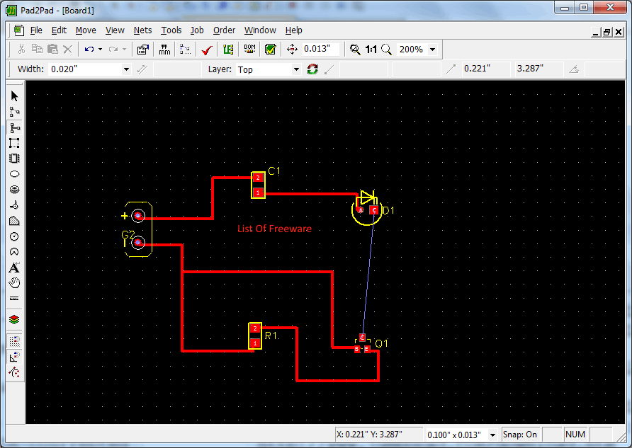
Pad2Pad is a free PCB design software through which you can order PCB online. You will find almost all components on this freeware which you may need to design any kind of PCB. The list of components include: Connector, Crystal, Dip, LED, Potentiometer, Relay, Transformer, Varistor, Resister, Capacitor, Inductor, Diode, Transistor, Battery, and many other parts.
It has option to import/export netlist (the list of components used along with specifications). After designing the circuit, save it in .pcb format, and you can even take a printout of the design.
Get help to design your circuit in this video guide.
ExpressSCH
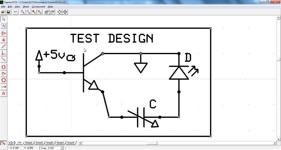
ExpressSCH is an easy to use circuit design program, and is used to develop schematic designs. Create a new project, and add components to arrange them as a digital circuit. Use components, like: Connectors, Wires, ICs, Opamps, Microchips, Micro controllers, Regulators, Converters, Amplifiers, Timers, Temperature, Sensors, LCD, Registers, etc.
You can easily change the orientation of any added component, rotate, or move them. Complete your circuit design and save it in .sch format. Export the design as image if you want to.
ExpressPCB
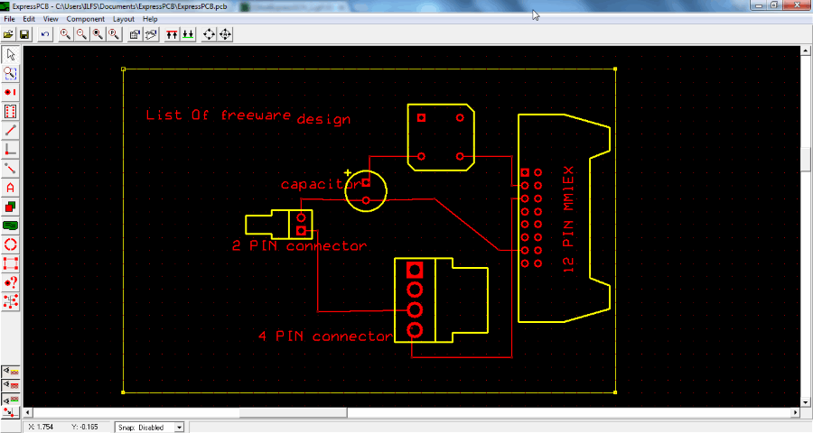
ExpressPCB is almost same as ExpressSCH, but instead of creating schematic design, it lets you make PCB design. Use the following components to design circuits on a Black background: Diode, Capacitor, Register, Connector , Crystal Oscillator, DIP, LED, PLCC, Semiconductor, Potentiometer, Switch, etc.
Save your PCB design in .pcb format or export as image. You may also export the design as a mechanical drawing in .dxf format.
Check errors in the circuit by the Check Schematic For Netlist Errors tool.


Harshwardhan Gupta
https://padangtoto-online.s3.wasabisys.com/index.html https://padangtoto.s3.us-west-004.backblazeb2.com/index.html
About Us

We are the team behind some of the most popular tech blogs, like: I LoveFree Software and Windows 8 Freeware.
More About UsArchives
- May 2024
- April 2024
- March 2024
- February 2024
- January 2024
- December 2023
- November 2023
- October 2023
- September 2023
- August 2023
- July 2023
- June 2023
- May 2023
- April 2023
- March 2023
- February 2023
- January 2023
- December 2022
- November 2022
- October 2022
- September 2022
- August 2022
- July 2022
- June 2022
- May 2022
- April 2022
- March 2022
- February 2022
- January 2022
- December 2021
- November 2021
- October 2021
- September 2021
- August 2021
- July 2021
- June 2021
- May 2021
- April 2021
- March 2021
- February 2021
- January 2021
- December 2020
- November 2020
- October 2020
- September 2020
- August 2020
- July 2020
- June 2020
- May 2020
- April 2020
- March 2020
- February 2020
- January 2020
- December 2019
- November 2019
- October 2019
- September 2019
- August 2019
- July 2019
- June 2019
- May 2019
- April 2019
- March 2019
- February 2019
- January 2019
- December 2018
- November 2018
- October 2018
- September 2018
- August 2018
- July 2018
- June 2018
- May 2018
- April 2018
- March 2018
- February 2018
- January 2018
- December 2017
- November 2017
- October 2017
- September 2017
- August 2017
- July 2017
- June 2017
- May 2017
- April 2017
- March 2017
- February 2017
- January 2017
- December 2016
- November 2016
- October 2016
- September 2016
- August 2016
- July 2016
- June 2016
- May 2016
- April 2016
- March 2016
- February 2016
- January 2016
- December 2015
- November 2015
- October 2015
- September 2015
- August 2015
- July 2015
- June 2015
- May 2015
- April 2015
- March 2015
- February 2015
- January 2015
- December 2014
- November 2014
- October 2014
- September 2014
- August 2014
- July 2014
- June 2014
- May 2014
- April 2014
- March 2014
