10 Best Free Logic Gate Simulator Software For Windows
This article contains a list of Best Free Logic Gate Simulator Software For Windows. These freeware can be used by students, researchers, or anyone else to design and simulate logic gates for analysis or some other purpose.
These free logic gate simulation software work in basically two steps, which are:
- Design: This is the first step where you have to draw your own circuit using logic gates. For this purpose, you can use components including input (switch, joystick, constant, etc.), output (LED, graphics array, buzzer, Hex display, etc.), connectors, and logic gates (basic, complex, derived). The number of inputs for a gate can vary too. All these provide text tool to add labels to each component for a visually appealing circuit diagram.
- Simulation: After designing the circuit, you can run logic gate simulation and view the output of a created logic circuit by varying input vectors.
Many of these let you view digital signals in Oscilloscope window. You can also view truth tables of designed circuits, get minimized boolean expressions, check whether your design is correct, analyze circuit, view circuit statistics, and do more. You can export the logical circuit as JPEG, PNG, GIF, BMP, etc. images.
You also get other digital components in these software, such as multiplexer, demultiplexer, adder, subtractor, divider, multiplier, register, counter, RAM, ROM, etc. So, you can also create complex digital circuits and simulate them in real-time.
My Favorite Logic Gate Simulator For Windows:
Logisim is my favorite logic gate simulator for Windows. It lets you design and simulate logic circuits and also views truth table, expression, and Product of Sums and Sum of Products simplifications. It also provides a variety of components to add to your logic circuit design, like multiplexer, demultiplexer, adder, subtractor, divider, and more.
Logic Friday is another good free logic gate simulator as it is easy to use and provides some desirable features including trace logic gates, auto redraw gate diagram, etc.
You may also like some best free Circuit Design Software, Filter Designer Software, and Oscilloscope Software for Windows.
Logisim

Logisim is a free and portable logic gate simulator for Windows. You can use this software on the go and design and simulate logic gates.
It provides all components to design a logic circuit using logic gates. These include input (button, joystick, keyboard, etc.), output (LED, hex digit display, etc.), wiring (splitter, probe, pin, tunnel, etc.), and gates (AND, OR, XOR, XNOR, NOR, etc.). Additional components provided in Logisim are multiplexer, demultiplexer, adder, subtractor, divider, multiplier, register, counter, RAM, ROM, etc. As you add a logic gate to your diagram, you can edit its attributes including number of inputs (maximum 32), label, label font, facing, data bits, etc.
Let’s checkout the simulation and analysis options you get in Logisim:
- If you have enabled simulation from Simulate menu, you can view circuit simulation live i.e. the value of output is displayed in real time. Other options in Simulate menu are Go Out To State, Go In To State, Tick Frequency, etc.
- Step Simulation is another feature which helps you find the points in an overall circuit whose value changes.
- You can use Analyze Circuit option from Project menu to see truth table, expression, and Product of Sums and Sum of Products simplifications. There is also a build circuit feature which builds a circuit for chosen expressions of an output.
- There is a Logging option too which helps you save log file with values of selected components in your circuit.
- You can view circuit statistics using the dedicated option from Project menu.
Logisim is a good logic gate simulator software which lets you customize options related to simulation too, including iterations until oscillations, gate output when undefined, toolbar, mouse, etc.
Logic Friday
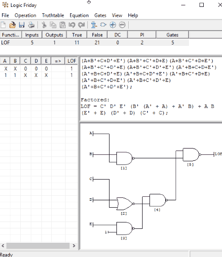
Logic Friday is another free logic gate simulator for Windows. You easily design and simulate logic gates using it. Let’s see how.
Design and simulate combinational logic circuit using logic gates:
- Go to File > New and select Gate Diagram. You can now design a logic circuit using multiple logic gates. You can add input, output, connector, 2, 3, and 4 input NAND, NOR, OR, and AND gates, inverters, 2 input XOR, and a 2-input multiplexer. After designing a desired combinational logic circuit, click on Submit button. As you do that, you will see output function and respective truth table of the created logical circuit.
- Using Gates menu, you can trace logic gates (shows the logic state of gates for chosen input vectors), IC package information, auto redraw gate diagram using built-in drawing engine, copy diagram to the clipboard, and do more.
- From the Operations menu, you minimize the boolean expression. The mode for the same can be Fast or Exact and for multiple outputs, you can select Independent or Joint minimization. Other tools contained in this menu include Map to Gate, Generate C Look Function, Clone Function, Compare Function, etc.
- The Equations menu is used to show sum of products, factored, product of sums, etc. equations for the selected function.
- Truth Table menu contains options like modify truth table, show True and Don’t Care, show all rows, invert selected outputs, etc.
Some other useful features of this free logic gate simulator:
- The gate diagram can be exported as EMF or BMP file or can be printed too.
- The truth table can also be saved (also opened) in CSV and TXT formats.
- You can enter a logic function and get respective truth table and vice-versa.
Logic Friday is another great software which can be used by students to learn about logic gates easily. But, it has a limitation that it can be used for a maximum of 16 inputs and outputs.
Deeds
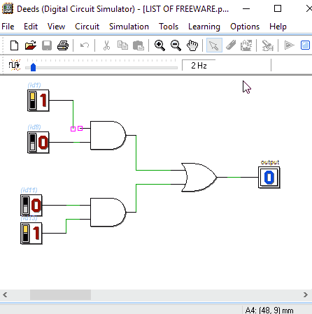
Deeds is another great logic gate simulator for Windows. Deeds stands for Digital Electronics Education and Design Suite which basically helps you learn about digital electronics working.
Let’s checkout the steps to use Deeds as a logic gate simulator:
- Gate Design: Firstly, you need to design a logic circuit using logic gates. For this, go to Circuit menu to see a sorted list of logic gate components and add desired components. You can insert inputs (switch, push button, hex digit, dip-switches), outputs (one bit, LED arrays, test LED, test points), wires, and logic gates (AND, OR, NAND, NOR, EXOR, NOT, etc.). Each individual logic gate can have a maximum of 8 inputs. And for each component, you can edit respective properties including label, initial value, etc. Advanced components to design a digital circuit include Decoder, Encoder, Multiplexer, Demultiplexer, Counters, Registers, Flip-Flops, etc. You can save the circuit design as an image (PNG, BMP) too.
- Simulation: After designing a combinational logic circuit using logic gates, go to Simulation menu and start the simulation. You will be able to view the output of the created circuit. It lets you enable or disable clock animation too. Also, you can vary the input vectors and check the respective output. There is a feature called Timing Diagram Simulation which can be used to trace signals, and the timing diagram can be saved as a PNG or BMP image. It also provides useful tools called Export VHDL (export to other design environment tools) and Test on FPGA (test created project on FPGA board).
Deeds also provides some other design tools named Finite State Machine Simulator and Micro-Computer Emulator. You can learn about these tools in detail on its official website.
Overall, Deeds is a great logic gate simulator with an easy-to-use interface. You also get Deeds demos and learning material to understand it better.
Hades
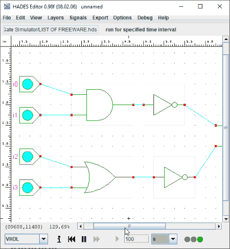
Hades is another free logic gate simulation software for Windows.
Design and simulate logic gates in Hades:
In order to simulate logic gates, just follow below steps:
- Open Hades and right click on the drawing area. You will see various options in the context menu, such as wire (connect, add probe, insert vertex, etc.), create, edit, etc. Simply choose the desired logic gate components from create option. You can add inputs, outputs, basic gates, and complex gates. As inputs and outputs, you can add switch, LED, hex display, clock generator, VCC, pullup, etc. Also, you can add components like flip-flop, RTL, etc. It also provides some demo circuits which you can utilize from Help > Demos option.
- The simulation of a designed circuit can be run from the bottom of the interface. The simulation can be customized by mode (VHDL, Real Time, Batch, etc.) and time.
- After creating a logic circuit, you can debug the circuit design and find out the errors in the diagram. There is also an option to correct highlighted errors, but it didn’t work fine during my testing.
- You can export the logical circuit as JPEG, PNG, GIF, PPM, Postscript, etc. files.
To view logic gates, you can enable instance labels, instance border, class labels, port labels, port symbols, bus port symbols, invert canvas, etc.
Hades is a portable logic gate simulation software. Although it is a decent software, many of the features weren’t working fine while my testing, such as performance statistics, print simulator status, etc.
MultiMedia Logic
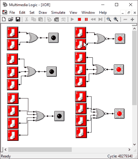
MultiMedia Logic is yet another digital circuit simulation program. The main interface of this software is well categorized into various menus. So, you can easily design and simulate logic gates.
Firstly, you need to go to Draw menu to add input (oscillator, switch, ground, plus, port in, signal receiver, timer, clock, keypad, etc.), output (LED, 8 segment LED, sound wave, signal sender, port out, bitmap, buzzer, etc.), wire, and logic gates components to design a combinational logic circuit. Or, you can use the tool palette provided by it to design a logic circuit. It lets you add up to 4 inputs to a particular logic gate. You get other components too to design a digital circuit, like multiplexer, memory, tape driver, etc. As you create a circuit, go to Simulate menu for live logic gate simulation. You can change input values and see the respective output. From Simulate > Setup, you can customize simulation rate and simulation conditions.
MultiMedia Logic is a simple logic gate simulator. It is one of the easiest software for logic gate simulation. You can print the designed logic circuit. Also, you can customize font, color wires, etc.
Logic Gate Simulator
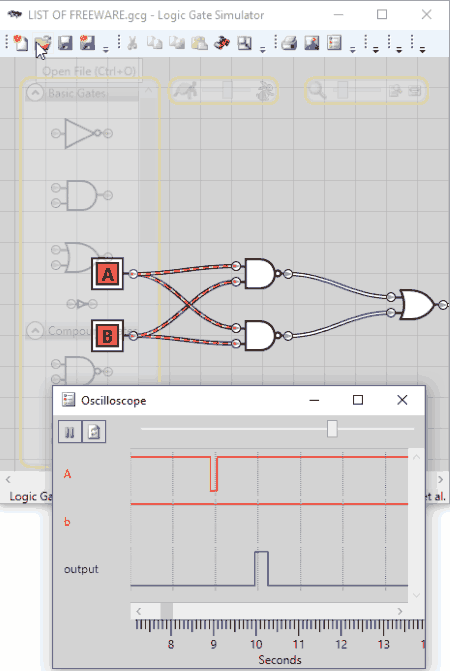
Logic Gate Simulator, as the name gives away, is a free and open source logic gate simulator for Windows. It comes with a variety of components to design a logic gate circuit and later simulate it.
You get basic gates (NOT, AND, OR, Inverter), compound gates (NAND, NOR, XOR, XNOR), and input/output gates (user/numeric input, user/numeric output, clock period in ms, comment, etc.) to draw a logical circuit. Just drag and drop the components to the drawing window and create a desired logic gate design. You can add multiple inputs to a gate, connect components using wire, rename components, etc. to further customize logic gates.
It shows real-time simulation of logic gates as you vary input vectors. Also, you can use Show Logical Analyzer button to view logic gate simulation in oscilloscope form with input and output signals.
Logic Gate Simulator is a nice and intuitive logic gate simulation software. It lets you print designed circuit, save circuit as an image (PNG, BMP, JPEG), create IC, import IC, flatten circuit, and do more.
Logical Circuit
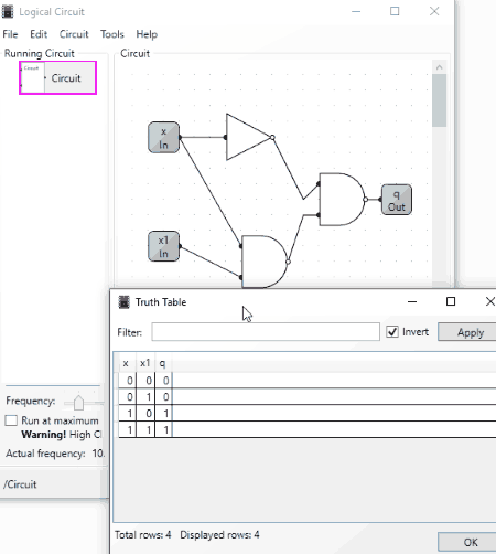
Logical Circuit is another one of logic gate simulator software in this list. Using it, you can design a logic circuit using inputs, outputs, basic logic gates, and memory components. As inputs and outputs, you can add pin, button, constant, sensor, clock, LED, LED matrix, splitter, graphics array, buzzer, probe, etc. In addition, you can edit properties of input/output components, such as description, bit width, side, notation, name, etc. For logic gates, you can add up to 18 inputs to each. You can also add text notes to your circuit design.
- After designing a logic circuit, you can check a project report with circuit description and functions.
- Also, it lets you view truth table of the corresponding logic circuit.
- You can use Tools > IronPython Console option to test your circuit. Check here for syntaxes to use scripts in logic circuits.
- By switching power on from Circuit menu, you can view actual frequency by running the circuit at maximum speed.
The designed circuit can be exported as an image in PNG, GIF, BMP, JPEG, or TIFF format.
Logical Circuit is a multilingual logic gate simulator. Apart from English, it supports German, Spanish, Greek, Italian, Korean, Chinese, etc. languages. Also, you can customize gate shape (rectangular, shaped), save changes automatically, etc. preferences.
CEDAR Logic Simulator
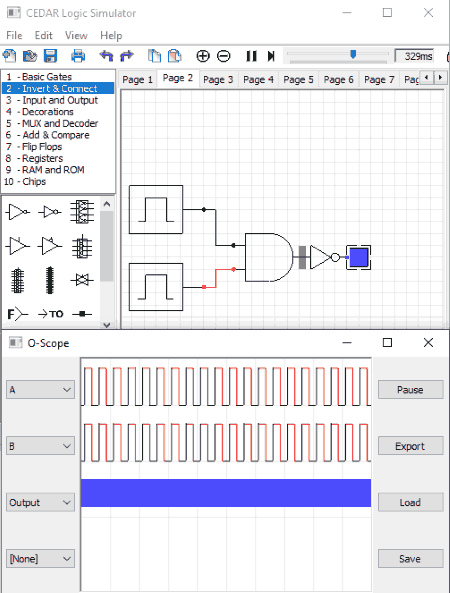
CEDAR Logic Simulator is another option as a logic gate simulator for Windows. It has a nice and easy user interface and is recommended for beginners.
The components to design logic circuit are available in the left pane of the interface. These include basic gates, inverter & connector, input and output, MUX and decoder, Flip Flops, etc. Just drag and drop a component to editing area and design your own circuit using logic gates. It shows the real-time simulation of logic gates. You can pause the simulation from its toolbar and change the simulation speed too.
After creating the design, you can use the View > Oscope option to view single value propagation throughout the designed circuit (see screenshot). It lets you export circuit design as a Bitmap image.
CircuitMod
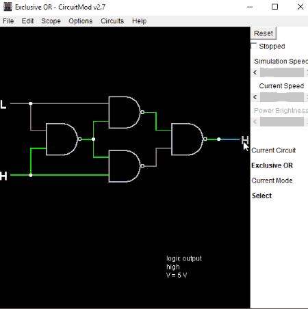
CircuitMod is a free circuit simulator software for Windows. It can be used to create simple as well as complex circuits with a wide range of components including passive filters, diodes, transistors, MOSFET, combination logic, resistors, capacitors, etc. It shows live circuit simulation by unchecking Stopped box from the right panel. You can adjust simulation speed too from there.
To create combinational logic gates, simply go to Circuit menu and choose logic gates to include in your circuit design. You can add input, output, wires, logic gates, and other essential components. As you create a circuit, you will be able to view its output. It lets you change the input values to high or low and you can set the respective input voltage value.
Digital Logic Design
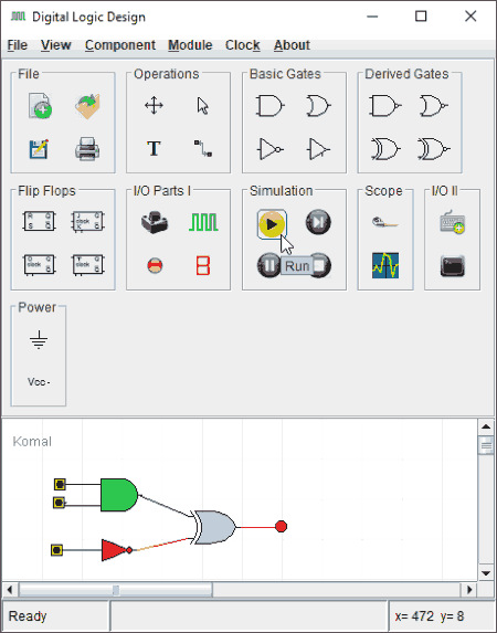
Digital Logic Design is yet another free and portable logic gate simulator software. Simulating logic circuits in this software is quite easy. The components like input and output, basic gates, and derived gates are present on its toolbar. Just drag and drop the components to its editing window and prepare your circuit design. After that, you can run a simulation using the dedicated tool from its toolbar. You can view digital signal in a separate oscilloscope window too.
It also lets you design a circuit using other components including adder, subtractor, encoder, decoder, Mux, Demux, etc.


About Us

We are the team behind some of the most popular tech blogs, like: I LoveFree Software and Windows 8 Freeware.
More About UsArchives
- May 2024
- April 2024
- March 2024
- February 2024
- January 2024
- December 2023
- November 2023
- October 2023
- September 2023
- August 2023
- July 2023
- June 2023
- May 2023
- April 2023
- March 2023
- February 2023
- January 2023
- December 2022
- November 2022
- October 2022
- September 2022
- August 2022
- July 2022
- June 2022
- May 2022
- April 2022
- March 2022
- February 2022
- January 2022
- December 2021
- November 2021
- October 2021
- September 2021
- August 2021
- July 2021
- June 2021
- May 2021
- April 2021
- March 2021
- February 2021
- January 2021
- December 2020
- November 2020
- October 2020
- September 2020
- August 2020
- July 2020
- June 2020
- May 2020
- April 2020
- March 2020
- February 2020
- January 2020
- December 2019
- November 2019
- October 2019
- September 2019
- August 2019
- July 2019
- June 2019
- May 2019
- April 2019
- March 2019
- February 2019
- January 2019
- December 2018
- November 2018
- October 2018
- September 2018
- August 2018
- July 2018
- June 2018
- May 2018
- April 2018
- March 2018
- February 2018
- January 2018
- December 2017
- November 2017
- October 2017
- September 2017
- August 2017
- July 2017
- June 2017
- May 2017
- April 2017
- March 2017
- February 2017
- January 2017
- December 2016
- November 2016
- October 2016
- September 2016
- August 2016
- July 2016
- June 2016
- May 2016
- April 2016
- March 2016
- February 2016
- January 2016
- December 2015
- November 2015
- October 2015
- September 2015
- August 2015
- July 2015
- June 2015
- May 2015
- April 2015
- March 2015
- February 2015
- January 2015
- December 2014
- November 2014
- October 2014
- September 2014
- August 2014
- July 2014
- June 2014
- May 2014
- April 2014
- March 2014
