6 Best Free Open Source PCB Design Software For Windows
Here is a list of best free open source PCB design software for Windows. Using these open source PCB design software, you can easily design a printed circuit board (PCB) consisting of tracks and components or components name. As all of these software are open source, hence you can also download and make modifications to the source code of any of these software.
In these software, you get various tools to design a PCB like PTH, Connectors, Arc, Polygon, etc. Plus, you can also find many electronic components (AnalogIC, Contributed Parts, DescreteSemi, etc.) which you can add to your PCB design. To differentiate tracks of PCB from each other, you can assign different colors to each track in some of these software. Plus, it is quite easy to assign a name to each track and component using the Text tool, that you can find in most of these software.
After completing a PCB design layout, these software let you save the design in Images (PNG, JPEG, BMP, etc.) and PDF document formats. A few of these software also let you export components and components connectivity information in the form of a Netlist. In a few of these software, you can also import a netlist to gather all the information about a PCB design. These software also offer some additional tools like Measure (to measure the distance between two points), Autoroute (to automatically create PCB path according to the selected components), 3D viewer (to view PCB design in 3D view), etc. Using available tools and features, you can easily create a PCB design. Go through the list to know more about these software.
My Favorite Open Source PCB Design Software For Windows:
Fritzing is my favorite software because it offers almost all the required tools which you may need to create a simple or complex PCB design. Plus, I like its ability to show entire code behind the PCB design.
You can also check out lists of best free Circuit Design, Circuit Simulation, and Open Source Diagram software for Windows.
Fritzing
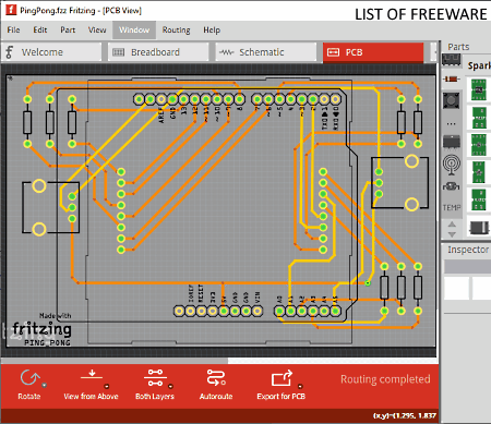
Fritzing is a free open source PCB design software for Windows, macOS, and Linux. Using this software, you can make a PCB design. Apart from PCB design, it also lets you create PCB schematics and breadboard designs. It offers a lot of inbuilt electronic parts which you can use in your PCB design. Plus, other important tools like Routing (to specify the connection between electronics components), Viewing, Layers, etc., are also present in it. The interface of this software is also quite interactive and user friendly.
How to design PCB using Fritzing:
- Launch this software and go to the PCB section of this software.
- After that, go to Parts panel and select a Parts section from various available ones such as Electromechanical, AnalogIC, Contributed Parts, DescreteSemi, etc.
- Now, select electronic components which you want to use in your PCB design and drop them over the main editing section of this software.
- Next, place all the components in the right position and then use Routing (connection) or Wire tools to start joining the components to complete the PCB design.
If you move to Breadboard and Schematic sections, you can view respective diagrams based on your PCB layout design. You can also access the code behind your PCB layout by going to the Code section.
After creating the PCB layout design, you can export it in Etchable PDF, Etchable SVG, and Image (PNG and JPG) formats.
Additional Features:
- Layer View: Using it, you can easily view below, above, and in between PCB layers.
- Autoroute: It is an advanced feature that automatically routes or join components according to the types of components used by you.
- Rotate: It is another handy tool that allows you to change the orientation of individual PCB components and PCB layout design.
Final Thoughts:
It is a comprehensive open source PCB design software through which you can create both simple and complex PCB designs.
Minimal Board Editor
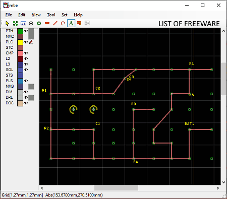
Minimal Board Editor is another free open source PCB design software for Windows. It is also a portable software that you can use on the go without actually installing it in your system. Through this software, you can create a PCB path layout, specify PCB components name and components’ connections. To do that, it offers various PCB designing tools like Connection Check, Measure, Arc, Text, Line, and more. After completing a PCB design, you can easily export it in PDF format. Plus, an option to export the components list and connection information of a PCB layout in the form of a Netlist (.net) is also provided by it.
How to design PCB using this open source PCB design software:
- Launch this software and select PTH (Plated Through Hole) tool from its interface and start placing them over its interface to specify PTH locations over the PCB.
- After that, select the Text tool and write names of components at different parts of the PCB to specify the locations of the component.
- Next, select the Line tool to create the PCB path that will determine the connection between different components of the PCB. At this time, you can also use other available tools to specify more connections like Arc, Polygon, Hole, Pad, etc.
- When done creating the PCB design, you can export it in a PDF document.
Additional Features:
- Color: It allows you to change the default colors of different components and path of the PCB layout.
- Measure: It is a handy tool that you can use to accurately measure the distance between any two points present over a PCB design.
Final Thoughts:
It is a simple and easy to use open source PCB design software through which you can create a PCB design without much hassle.
Note: On the provided download page, please scroll down to Minimal Board Editor software to get its download link.
FreePCB
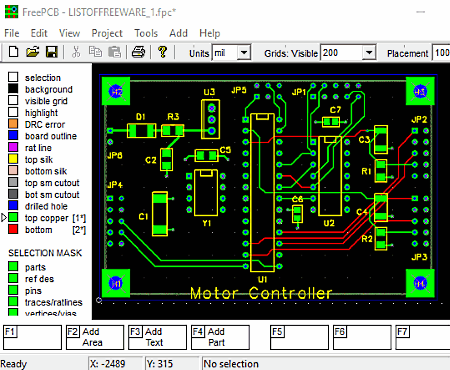
FreePCB is yet another free open source PCB design software for Windows. Through this software, you can create a PCB layout using various available PCB designing tools. The process of creating a PCB design is also quite simple in this software. You can access all the required PCB components from the Part section and all the connecting tools like line, arc, etc., from the bottom part of its interface. Before designing the PCB layout, you can adjust the PCB units (mil or mm), Visible grid area (1 mm, 2mm, 5mm, etc.), and Routing line width (1mm, 4 mm, etc.) using Toolbar tools. From the Leftside panel of this software, you can also manually change the color of different connections and routing lines in this software.
How to design PCB using this open source PCB design software:
- Open the interface of this software and create a new project.
- After that, go to Project tab and select PCB components which you want to put in your PCB layout.
- Next, use Routing tools to specify the path of copper lining over the PCB board to complete the PCB design.
- Lastly, use the Save option to store the PCB design as a local project file or use the Export CAM option to save the design in a CAM file. You can also export the components list as a Netlist file.
Additional Features:
- Check Connectivity: It helps you find out all the broken connections or unconnected components present in your PCB layout design.
- Design Rule Check: It checks your PCB design according to PCB design rules to find wrong connections and faulty PCB design.
Final Thoughts:
It is another decent open source PCB design software that anyone can use to create good PCB designs.
KiCad EDA
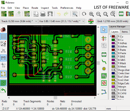
KiCad EDA is the next free open source PCB design software for Windows, Ubuntu, Linux, MacOS, OpenSUSE, etc., operating systems. In this software. you get many different modules like Gerber Viewer, Page Layout editor, Pcbnew, etc. From various available modules, you need to use its Pcbnew module to create a PCB design. In the Pcbnew module, you can find a large PCB designing area along with various PCB designing tools like Add footprints, Add vias, Add graphics line, Add graphics arc, Add text, Add layer alignment, etc. It also allows you to load an external Netlist to quickly import all the required PCB components and connections’ information of a PCB design.
How to design PCB using this open source PCB design software:
- Launch this software and select Pcbnew module.
- After that, use available PCB designing tools and components to create a PCB design. You can use your mouse to specify the position of tracks and connections over the editing area.
- Next, use the Text tool to name the components and track names.
- Lastly, use the Export option to save the PCB design in formats like GenCAD, VRML, STEP, SVG, etc. You can also export PCB design in various fabrication output formats like .pos, .drl, .rpt, etc.
Additional Features:
- Measure: Using it, you can accurately measure the distance between components and lengths of connections between components.
- Design Rules Check: This feature checks whether the PCB design created by you follows the PCB designing rules or not.
- 3D Viewer: This feature lets you view individual components and the whole PCB design in a 3D view.
Final Thoughts:
It is another very capable open source PCB design software through which you can create great PCB designs.
FidoCadJ
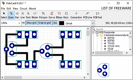
FidoCadJ is one more free open source PCB design software for Windows, macOS, Linux, and Android. Through this software, you can quickly create a PCB design layout as it offers all the essential PCB components and connecting lines on its interface. All the components (PCB Footprints, PCB Symbols, Electrical Symbols, etc.) are present on the right-side panel and all the connection tools (PCB Line, Polygon, Bezier, Text, etc.) are present on the toolbar of this software. Using available tools, you can easily create a PCB design as you want.
How to design PCB using FidoCadJ:
- Open the interface of this software and select one component at a time from its right-side panel and place it over the PCB editing area. Similarly, you can add more PCB components to your PCB design.
- After that, use connection lines from the top toolbar and start connecting the components. To differentiate the copper side connection from the component side connection, you can choose either copper side or component side option that assigns a color to the selected connection.
- Once the PCB design gets completed, use the Print option to save the design in PDF format and use the Export option to save the design in formats like PNG, JPEG, SVG, EPS, etc.
Additional Features:
- View Code: Using it, you can view the actual code behind a PCB design created by you.
- Image as background: It allows you to set an external image as a background of a PCB design.
Final Thoughts:
It is another simple and easy to use open source PCB design software that anyone can use without much hassle.
SimulIDE
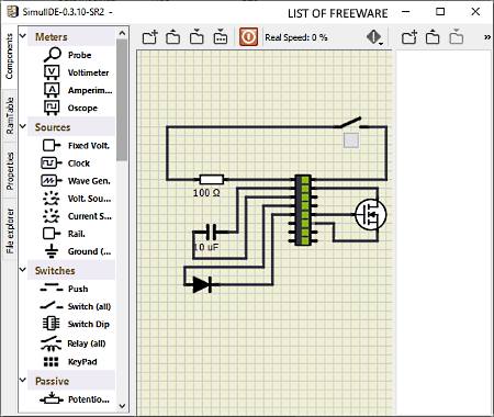
SimulIDE is yet another free open source PCB design software for Windows and Linux. It is primarily a circuit design software that can also be used to design PCB layouts. The unique thing about this software is that it can also simulate the circuit and the behavior of its components at different frequencies. The process of designing a PCB circuit layout through this software is pretty simple.
How to design PCB using SimulIDE:
- Open the interface of this software and go to its Components section where you can find a lot of components like stepper, gates, converters, ICs, text tool, and more.
- After that, drag and drop components which you want to use in your PCB design to the main editing area of this software.
- Next, start joining the components with the use of your mouse.
- After joining the components, use the text tool to name each component.
- Now, you can save your PCB design in image formats like PNG, JPG, BMP, SVG, etc.
Additional Feature:
- Power Circuit: It allows you to start the simulation that you can use to check the behavior of your design at different frequencies.
Final Thoughts:
This open source PCB design software not only lets you create PCB design, but you can also create and simulate a circuit design in it.
Naveen Kushwaha
Passionate about tech and science, always look for new tech solutions that can help me and others.
About Us
We are the team behind some of the most popular tech blogs, like: I LoveFree Software and Windows 8 Freeware.
More About UsArchives
- May 2024
- April 2024
- March 2024
- February 2024
- January 2024
- December 2023
- November 2023
- October 2023
- September 2023
- August 2023
- July 2023
- June 2023
- May 2023
- April 2023
- March 2023
- February 2023
- January 2023
- December 2022
- November 2022
- October 2022
- September 2022
- August 2022
- July 2022
- June 2022
- May 2022
- April 2022
- March 2022
- February 2022
- January 2022
- December 2021
- November 2021
- October 2021
- September 2021
- August 2021
- July 2021
- June 2021
- May 2021
- April 2021
- March 2021
- February 2021
- January 2021
- December 2020
- November 2020
- October 2020
- September 2020
- August 2020
- July 2020
- June 2020
- May 2020
- April 2020
- March 2020
- February 2020
- January 2020
- December 2019
- November 2019
- October 2019
- September 2019
- August 2019
- July 2019
- June 2019
- May 2019
- April 2019
- March 2019
- February 2019
- January 2019
- December 2018
- November 2018
- October 2018
- September 2018
- August 2018
- July 2018
- June 2018
- May 2018
- April 2018
- March 2018
- February 2018
- January 2018
- December 2017
- November 2017
- October 2017
- September 2017
- August 2017
- July 2017
- June 2017
- May 2017
- April 2017
- March 2017
- February 2017
- January 2017
- December 2016
- November 2016
- October 2016
- September 2016
- August 2016
- July 2016
- June 2016
- May 2016
- April 2016
- March 2016
- February 2016
- January 2016
- December 2015
- November 2015
- October 2015
- September 2015
- August 2015
- July 2015
- June 2015
- May 2015
- April 2015
- March 2015
- February 2015
- January 2015
- December 2014
- November 2014
- October 2014
- September 2014
- August 2014
- July 2014
- June 2014
- May 2014
- April 2014
- March 2014
