6 Best Free Ladder Diagram Software For Windows
Here is a list of best free ladder diagram software for Windows. Ladder diagrams or elementary diagrams are used to represent the function of a control circuit and its associated devices. However, a ladder diagram doesn’t show components of the control circuit nor their actual positions. Ladder diagram basically represents PLC circuits in much simpler way irrespective of the complexity of its control circuit. In order to create ladder diagrams, I have created this list that contains various ladder diagram making software.
Using these ladder diagram software, you can easily create all types of ladder diagrams. To make diagram designing easy, these software provide all essential ladder diagram elements. With the use of the mouse, you can drop required elements to the canvas and join them according to the diagram design. Along with creating the ladder diagram, you can also simulate the working of the ladder design in most software. The simulation gives the ideal about the real world performance of the diagram design. In some software, you can also load the ladder diagram or logic to a PLC device.
My Favorite Ladder Diagram Software For Windows:
ZelioSoft is my favorite software because it lets you can create and simulate the working of a ladder diagram. Plus, it also provides advanced program loading features through which you can load the ladder logic program to ZelioSoft Smart Relay.
You can also check out lists of best free Class Diagram Maker, Use Case Diagram, and ER Diagram Creator software for Windows.
ZelioSoft
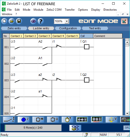
ZelioSoft is a free ZelioLogic Smart Relay programmer software for Windows. It can be used as a ladder diagram software because it uses the ladder diagram and FBD language to program the Smart Relay. In it, you can create the whole ladder diagram from the scratch or you can edit various inbuilt examples of the ladder diagram. In both the cases, the first step to create a diagram is by selecting the ZelioLogic relay type from various available ones. When you select a specific type relay module, then you get a Ladder Entry Section or Canvas. Just below the canvas, you get all components required to create a ladder diagram, such as multiple discrete inputs, Zx keys, auxiliary relays, discrete outputs, timers, counters, fast counters, and more. You can easily select and add one component at a time to the canvas to create ladder diagram.
In this software, you cannot only create the ladder diagram, but you can also run the simulation by switching from Editing to Simulation mode. In the simulation mode, you get a Run button and by pressing it, you can start the simulation. During the simulation, you can simulate a very important power failure scenario that shows the characteristics of your diagram in case of power failure. After the simulation, you can save the diagram as a ZelioSoft project file and PDF formats.
As this software is mainly a smart relay programmer software, hence you can also load your ladder diagram to program the smart relay device by physically connecting the device with your system.
YottaEditor
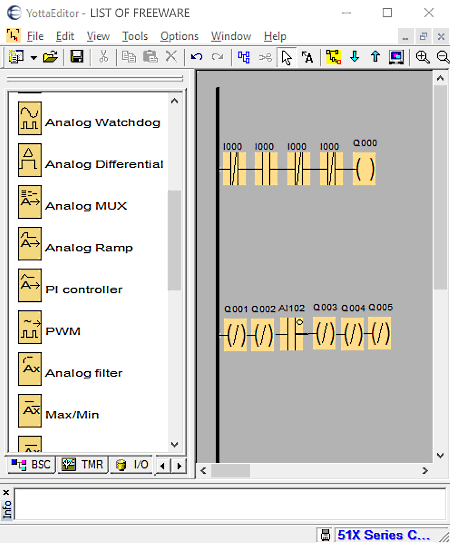
YottaEditor is another free ladder diagram software for Windows. It is a very comprehensive ladder diagram software through which you can create both simple and complex ladder diagrams. It provides various elements sections containing both conventional as well as advanced components which are usually not present in a ladder diagram software.
Let’s take a look at all the element sections and which elements they offer:
- I/O: In this section, you get all standard ladder diagram elements like make/ break contact, analog contact, relay contact, inverted output, etc.
- TMR: It contains pulse and timer related components such as Wiping Relay, Asynchronous Pulse Generator, Random Generator, Weekly Timer, Astronomical Clock, etc.
- Aux: In it, you get auxiliary components like Boolean Function, Binary Code, OR Mask, NOT Mask, Stepping Motor Control, Pulse Train Output, and more.
- Math: This section contains advanced math components or elements which you can include in the diagram such as Logarithm, Square Root, Sine Function, Cosine Function, Secant function, etc.
- BSC: It has only two components namely AND(Edge) and NAND(Edge).
You can easily select and add components or elements from element sections to the main canvas with ease. After adding all required elements to the canvas, join elements with the help of mouse to complete the ladder diagram. In it, you also get an inbuilt simulation feature through which you can perform simulation on your ladder diagram to check its performance.
Ladder diagram created through this software can be saved as YLD and PDF files.
ClassicLadder
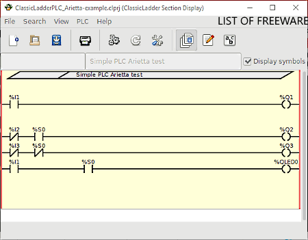
ClassicLadder is yet another free ladder diagram software for Windows. This software is mainly used to create programs for PLC or Programming Logic Controllers. It uses ladder programming language to program logic circuits. For ladder logic circuits, you need to create a ladder diagram. To create a ladder diagram, it provides an empty canvas along with an Editor section. Its editor section contains all essential ladder diagram components like N.O. Input, N.C. Input, Rising Edge Input, Falling Edge Input, N.C. Output, Counter block, etc. Before dropping essential elements to the canvas, you also get options to change the properties and values of the elements according to requirements. Once the values of each element get specified, just drop elements to the canvas and structure them according to the design to complete the ladder diagram.
In this software, you can also simulate the logic of the diagram using its Run logic feature. In the simulation, you can view the working of the ladder diagram. At any time, you can stop the simulation and make changes on the diagram to create different scenarios. After simulation, you can save the diagram as classLadder project or as SVG and PNG image formats.
TRiLOGI
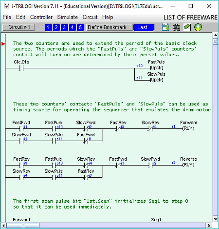
TRiLOGI is the next free ladder diagram software for Windows. In this software, you can create the whole ladder diagram from scratch as well as quickly edit previous ladder diagrams. For quick editing, it provides some dedicated features such as Insert Circuit, Move Circuit, and Append Circuit. To create a completely new diagram, you can use its I/O Table present inside the Edit Menu. The I/O Table contains various element sections such as Input elements, Output Elements, Relays, Timers, Counters, Cust Functions, etc. From these sections, you can select all the required elements to create a ladder diagram. The process of creating a ladder diagram is pretty simple as you just need to add and join components one by one in a sequential manner.
This software also lets you simulate the newly created ladder diagram just like other similar software. During the simulation, you can also change the values of components to simulate multiple scenarios.
Note: This education version of this software is free for only non-commercial usage. Plus, various features like program transfer to PLC, on-line monitoring, connect to the server, etc., are also locked.
Dia Diagram Editor
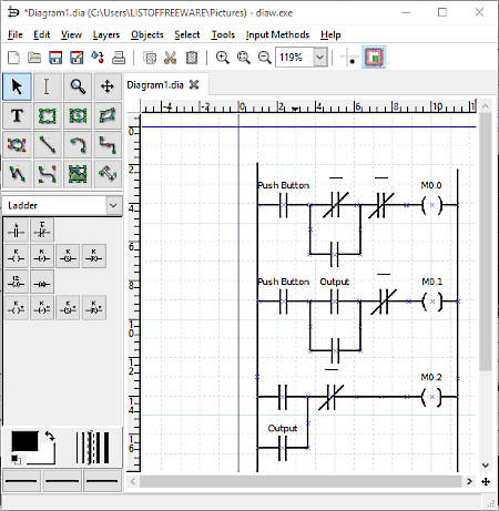
Dia Diagram Editor is a free open source ladder diagram software for Windows. Using this software, you can easily create a ladder diagram. Not just the ladder diagram, but a lot of different types of diagrams such as ERD, Network Diagram, Use Case Diagram, UML Diagrams, etc., can also be created in it. To deal with different types of diagram, it provides various dedicated sections containing tools to create a specific type of diagram like Assorted, Chronogram, Cybernetics, Database, etc. For the ladder diagram, you can use its Ladder section that has all essential shapes and elements like if ladder contact, if not ladder contact, simple output variable, negative output variable, receptivity output variable, and more.
You can easily select and drop ladder diagram elements from the ladder section to canvas to start building the diagram. The canvas available in it is also quite handy as it provides helpful features namely grid lines and a scale for precise diagram building. After dropping required elements to the canvas, you need to properly structure them by placing all elements on their right place. After making the structure, name each element of the ladder diagram to finish the diagram. After completion, you can export the ladder diagram in formats like PDF, SVG, PNG, TIFF, JPG, BMP, etc.
Ladder Master
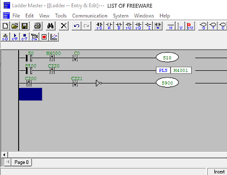
Ladder Master is a free programming software through which you can create and edit programs for PLC devices. It can also be used as a ladder diagram software because it uses ladder logic to program a PLC device. All essential components to create a ladder diagram or logic are available on its toolbar. From the toolbar, you can select and add elements to the canvas to create a ladder diagram. Some of the diagram elements that you get in the toolbar are Contact A, Contact B, Contact Pulse, Inverter, Out, Timer, Counter, etc. When you select an element, then you immediately get an option asking you to specify a specific version of that element by providing the element number. If you don’t have an idea about the component number, then you can use its Ref menu that contains all the versions of a selected component. Once the diagram gets completed, you can save it in a PLC file.
The ladder diagram or logic created in this software can also be compiled to check the feasibility and errors of that logic before loading it to a PLC device. In this software, you can find more PLC programming specific features such as Upload PLC to PC, Download PC to PLC, PLC Password Settings, PLC Initialize, and more.


Naveen Kushwaha
Passionate about tech and science, always look for new tech solutions that can help me and others.
About Us

We are the team behind some of the most popular tech blogs, like: I LoveFree Software and Windows 8 Freeware.
More About UsArchives
- May 2024
- April 2024
- March 2024
- February 2024
- January 2024
- December 2023
- November 2023
- October 2023
- September 2023
- August 2023
- July 2023
- June 2023
- May 2023
- April 2023
- March 2023
- February 2023
- January 2023
- December 2022
- November 2022
- October 2022
- September 2022
- August 2022
- July 2022
- June 2022
- May 2022
- April 2022
- March 2022
- February 2022
- January 2022
- December 2021
- November 2021
- October 2021
- September 2021
- August 2021
- July 2021
- June 2021
- May 2021
- April 2021
- March 2021
- February 2021
- January 2021
- December 2020
- November 2020
- October 2020
- September 2020
- August 2020
- July 2020
- June 2020
- May 2020
- April 2020
- March 2020
- February 2020
- January 2020
- December 2019
- November 2019
- October 2019
- September 2019
- August 2019
- July 2019
- June 2019
- May 2019
- April 2019
- March 2019
- February 2019
- January 2019
- December 2018
- November 2018
- October 2018
- September 2018
- August 2018
- July 2018
- June 2018
- May 2018
- April 2018
- March 2018
- February 2018
- January 2018
- December 2017
- November 2017
- October 2017
- September 2017
- August 2017
- July 2017
- June 2017
- May 2017
- April 2017
- March 2017
- February 2017
- January 2017
- December 2016
- November 2016
- October 2016
- September 2016
- August 2016
- July 2016
- June 2016
- May 2016
- April 2016
- March 2016
- February 2016
- January 2016
- December 2015
- November 2015
- October 2015
- September 2015
- August 2015
- July 2015
- June 2015
- May 2015
- April 2015
- March 2015
- February 2015
- January 2015
- December 2014
- November 2014
- October 2014
- September 2014
- August 2014
- July 2014
- June 2014
- May 2014
- April 2014
- March 2014
